Sieht das CAM Signal so richtig aus -> Bild
Verfasst: Sa Sep 05, 2020 4:17 pm
Hallo,
meinen alten Motor möchte ich auf Full Sequential umbauen. Dazu habe ich jetzt den alten Zündverteiler umgebaut. Von dern vier Nocken habe ich drei entfernt und die Verstellung blockiert.
Mit dem Nocken wird der Unterbrecher geöffnet. Als Schaltung auf der MS2 V3 nehme ich folgendes:
5.2.14.2 Adding a cam sensor input - hall sensor / optical sensor
This option uses the spare opto-isolator on the mainboard for the cam input and matches the polarity inversion
of the VR/universal tach input. This section is for open-collector sensors as covered in 5.2.3 that ground switch only.
a) The OptoIn pad should be connected to a spare pin on the main DB37 connector (e.g. SPR3)
c) 2014-5 James Murray 2015-07-09 Page 73/201 MS2V3.0 Hardware Guide
b) Connect OptoOut to JS10 (ensuring that nothing else is connected.)
c) Jumper XG1 - XG2
d) Check that R12 is a 390R to 470R resistor, replace if not.
e) Install a 470R 1/4W resistor on the proto area to +5V.
f) Jumper the other end of the 470R resistor to OptoIn (joining the jumper wire there.)
g) Ensure that C30 is not fitted.
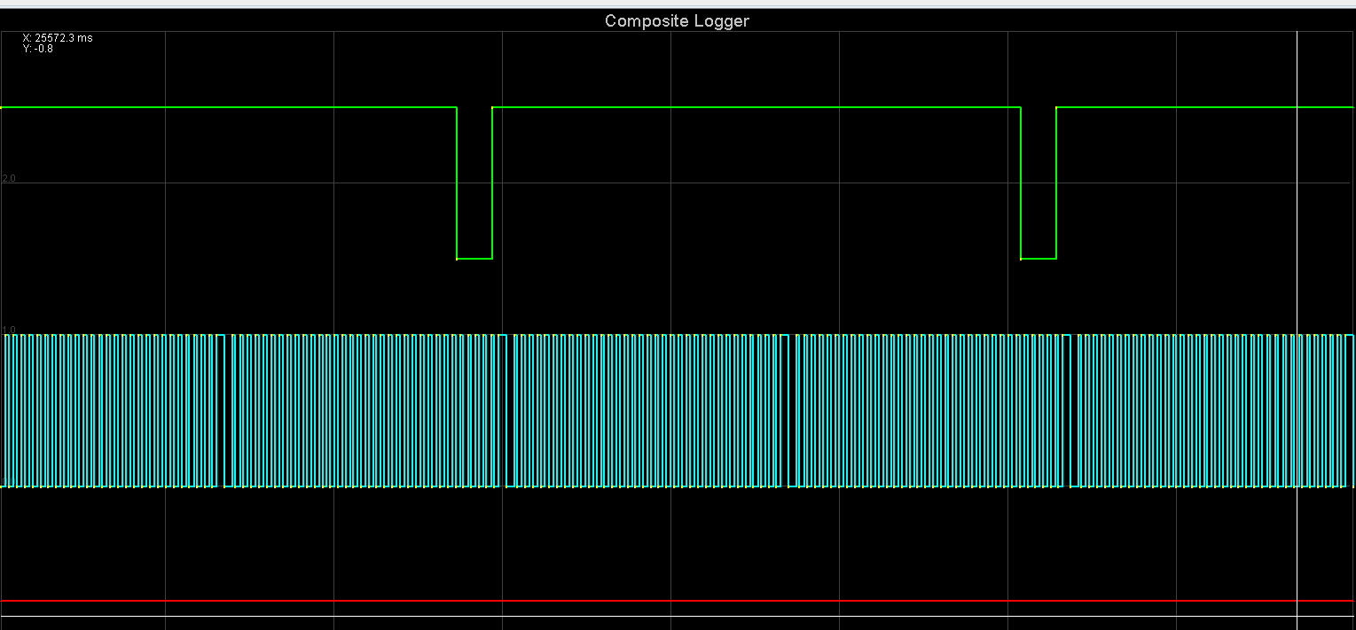
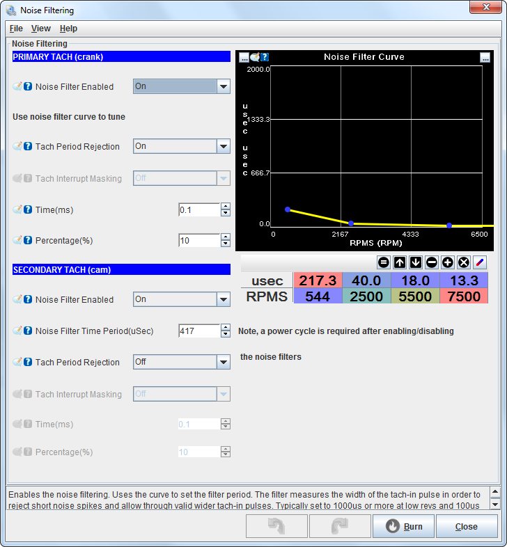
Ich wundere mich jetzt ein wenig dass das Cam Signale im Composite Logger so aussieht wie auf dem Bild. Ich hätte erwartet, dass es invertiert ist sprich lange Low (da der Unterbrecher zu ist und auf Ground schaltet) und eine kurze Zeit High wenn der Unterbrecher beim Nocken offen ist und der PullUp das Signal hochzieht. Als Noise Filter habe ich den Cam Filter aktiviert da sonst nur kurze High Spikes im Logger zu sehen sind.
Für die Kurbelwelle habe ich ein 36-1 Rad welches schon länger zuverlässig funktioniert.
Mein Tooth 1 Angel steht bei 129° BTDC, das Cam Signal kommt dann nochmal 30° früher. Laut Anleitung sollte das so richtig sein?
Ich habe noch nicht die Schaltung für die getrennten EVs eingebaut. Muss ich für Batch-Fire 2 Squirts Alternating einstellen damit es wie bisher ist?
Danke
Thomas
meinen alten Motor möchte ich auf Full Sequential umbauen. Dazu habe ich jetzt den alten Zündverteiler umgebaut. Von dern vier Nocken habe ich drei entfernt und die Verstellung blockiert.
Mit dem Nocken wird der Unterbrecher geöffnet. Als Schaltung auf der MS2 V3 nehme ich folgendes:
5.2.14.2 Adding a cam sensor input - hall sensor / optical sensor
This option uses the spare opto-isolator on the mainboard for the cam input and matches the polarity inversion
of the VR/universal tach input. This section is for open-collector sensors as covered in 5.2.3 that ground switch only.
a) The OptoIn pad should be connected to a spare pin on the main DB37 connector (e.g. SPR3)
c) 2014-5 James Murray 2015-07-09 Page 73/201 MS2V3.0 Hardware Guide
b) Connect OptoOut to JS10 (ensuring that nothing else is connected.)
c) Jumper XG1 - XG2
d) Check that R12 is a 390R to 470R resistor, replace if not.
e) Install a 470R 1/4W resistor on the proto area to +5V.
f) Jumper the other end of the 470R resistor to OptoIn (joining the jumper wire there.)
g) Ensure that C30 is not fitted.
Ich wundere mich jetzt ein wenig dass das Cam Signale im Composite Logger so aussieht wie auf dem Bild. Ich hätte erwartet, dass es invertiert ist sprich lange Low (da der Unterbrecher zu ist und auf Ground schaltet) und eine kurze Zeit High wenn der Unterbrecher beim Nocken offen ist und der PullUp das Signal hochzieht. Als Noise Filter habe ich den Cam Filter aktiviert da sonst nur kurze High Spikes im Logger zu sehen sind.
Für die Kurbelwelle habe ich ein 36-1 Rad welches schon länger zuverlässig funktioniert.
Mein Tooth 1 Angel steht bei 129° BTDC, das Cam Signal kommt dann nochmal 30° früher. Laut Anleitung sollte das so richtig sein?
Ich habe noch nicht die Schaltung für die getrennten EVs eingebaut. Muss ich für Batch-Fire 2 Squirts Alternating einstellen damit es wie bisher ist?
Danke
Thomas